Computer Graphics Raytracing project
1. The framework
In this assignment you will setup the environment for your ray tracer implementation. A note on programming languages: the framework we provide is written in C++, however, you are free to use any other language (but be sure your raytracer works on the lab machines).
Tasks:
- Install the source code of the ray tracer framework. The C++ version comes in four different flavors:
- For gcc: Raytracer.zip
- As a Microsoft Visual Studio Project: Raytracer-msvc.zip
- For Microsoft Visual Studio .NET 2003: raytracer-vsnet2003.zip
- For Dev-C++: raytracer.dev.start.zip
Compile it and test whether it works. Using the supplied example scene rt1.in the following image should be created:
- Look at the source code of the classes and try to understand the program. Of particular importance are the files
vector.h and color.h which define mathematic operators on vectors, points, rays, and colors. The actual raytracing algorithm is implemented in raytracer.h and raytracer.cpp.
2. Raycasting with spheres
In this assignment your program will produce a first realistic image of a 3D scene using a basic ray tracing algorithm, for now without reflection or refraction. This non-recursive variant of ray tracing – also called ray casting – determines which surfaces are visible and uses a local lighting model to produce shading.
- The program should be able to handle at least 5 spheres. Adding more spheres is not hard, but the calculations will take more time. Each sphere is given by its midpoint, its radius, and its surface parameters (color and parameters for Phong shading).
- The white point-shape light source is given by its position (x,y,z). Multiple, colored light sources is not yet necessary.
- The viewpoint is given by its position (x,y,z). To keep things simple the other view parameters are static: the image plane is at z=0 and the viewing direction is along the negative z-axis.
- The scene description is read from a file.
Tasks:
- Implement the intersection calculation for the sphere. Extend the function
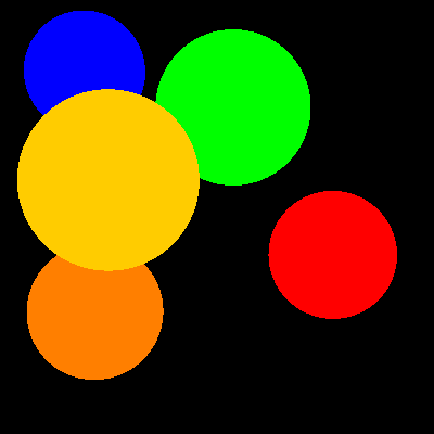
Sphere::intersect() in the file sphere.cpp. The resulting image should be similar to the following image:
- Implement the normal calculation for the sphere. To this end, complete the function
Sphere::normal() in the file sphere.cpp. Because this function is not used yet, the resulting image will not change.
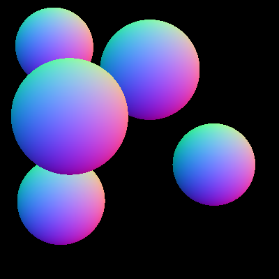
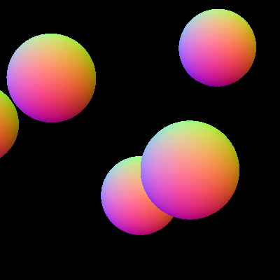
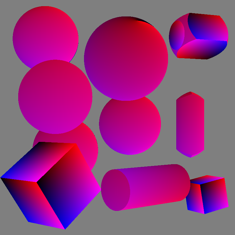
- Adapt your program such that it can also a produce a normal buffer image instead of the normal rendering (this should be configurable in the scene file). Map the three components of a normal to the three colors (be sure to map the possible range of the components (-1..1) to the range of the colors). Two example normal buffer images (of two different eye positions):
- Implement the diffuse term of Phong's lighting model to obtain simple shading. Modify the function
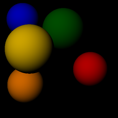
Raytracer::trace(Ray) in the file raytracer.cpp. This step requires a working normal calculation. The resulting image should be similar to the following image:
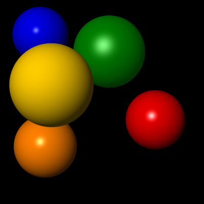
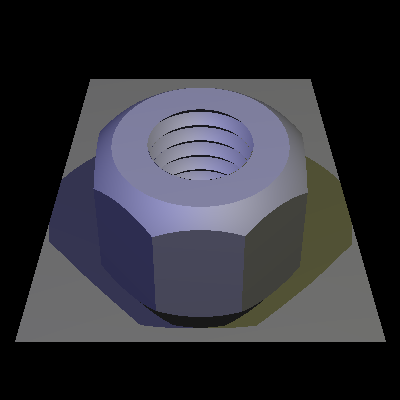
- Extend the lighting calculations with the ambient and specular parts of the Phong model. This should yield the following result:
- (Bonus) Experiment with your own scene descriptions. Even with just spheres you can build some interesting scenes!
3. Export z-buffer image and anti-aliasing
In raytracing, Hidden Surface Removal (HSR) is basically included in the technique and you are using (without noticing) a z-buffer-like algorithm in your raytracer. In this assignment you will gain a deeper understanding of this process. This assignment is concluded with anti-aliasing, which will result in better looking images.
Tasks:
- Adapt your program such that it can also produce a z-buffer image instead of the normal rendering (this should be configurable in the scene file). Use gray levels to code distances. An example z-buffer image:
- Implement super-sampling (anti-aliasing), i.e., casting multiple rays through a pixel and averaging the resulting colors. This should give your images a less jagged appearance. An example of 4x4 super-sampling:
4. Optical laws
In this assignment you will implement a global lighting simulation. Using recursive ray tracing the interaction of the lights with the object is determined. The program should be able to handle multiple colored light sources and shadows.
Tasks:
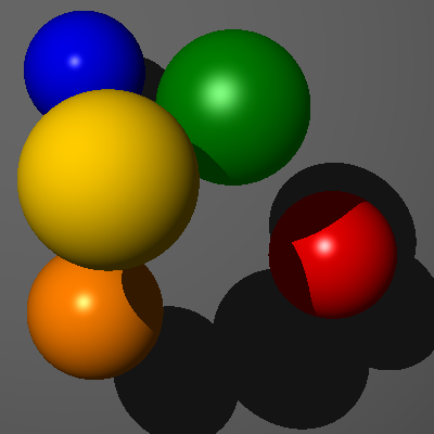
- Extend the lighting calculation in
Raytracer::trace(Ray) such that it produces shadows. To achieve this you should test whether a ray from the light source to the object intersects other objects. Only when this not the case, the light source contributes to the lighting. For the following result a large background sphere is added to the scene (material grey, ambient 0.2, diffuse 0.8, position [200,200,-1000], radius 1000).
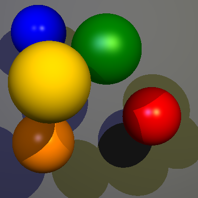
- Now loop over all light sources and use their color in the calculation. For the following result image two light sources were used: bluish light (.4,.4,.8) at [-200,600,1500], a yellowish light (.8,.8,.4) at [600,600,1500].
- Extend the class
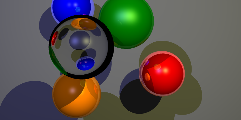
Material in the file material.h with three parameters: reflect, refract, and eta. Also extend the read function in material.cpp. Test your changes with the scene file rt2.in.
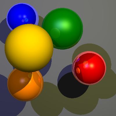
- Implement reflections, by recursively continuing rays in the direction of the reflection vector, using the
reflect parameter. Example result:
- Implement refraction, by recursively continuing rays in the direction of the transmission vector, using the parameters
refract and eta, where eta is the index of refraction of the material.
- (Bonus) Test your implementation using a scene you designed yourself.
5. Texture mapping and extended camera model
Tasks:
- Implement an extended camera model such that other image resolutions are possible and producing images becomes more flexible. You can use Andrew Glassner's "A Simple Viewing Geometry" as a starting point. An example of what this could look like:
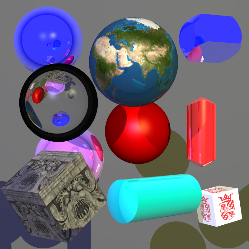
- Implement texture mapping. With textures it becomes possible to vary the lighting parameters on the surface of objects. For this a mapping from the points of the surface to texture-coordinates is needed. See Links and References for links to example textures to use.
- (Bonus) Implement bump-mapping.
The results could be something similar to the following (texture coordinates, texture mapping, bump mapping, normal buffer):
6. Alternative illumination models
In particular for illustration purposes alternative illumination models have been developed, which are rather easy to implement in your raytracer. In this assignment you will implement one of these models.
Tasks:
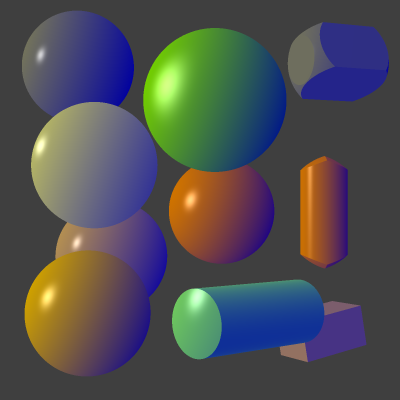
- Implement the illumination model by Gooch et al. Be aware of the following:
- The formula for the lighting calculation in the original paper is not correct. Use this one: I = kCool *(1 - NL)/2 + kWarm * (1 + NL)/2.
- Extend the scene description for the new parameters.
- The Gooch model should not replace the Phong model, instead which model will be used should be configurable.
The resulting image could look like the following:
7. Other geometries and 3D mesh files
To be able to create some more interesting scenes you will in this assignment extend the number of types of geometries your raytracer can handle. Only three things need to be added for each new geometry type:
- Reading in the parameters
- Intersection calculation
- Normal calculation
Tasks:
- Implement four other geometry types (at least cylinder and triangle). Use the following list for inspiration:
- Quad
- Planes (determined by a point and a normal)
- Polygon (determined by corner points)
- Cylinder, Cone, parabolic surfaces
- Torus (can have 4 intersections points)
- Blobs
- Free-form surfaces
- Implement 3D mesh objects (read from a file). Use the code (
glm.c and glm.h) you used in the OpenGL Project (just remove the drawing code, this way you do not have to link to OpenGL). You can use the same models, but be aware that producing a raytraced image of a model with many triangles can take a long time. For example, the following image of an evil golden rubber duck (with 3712 triangles) took almost nine hours to generate on a reasonably fast machine (with 3x3 super-sampling, relatively unoptimized code).
- (Bonus) Implement constructive solid geometry (CSG). Here is an example of a rendering with cylinders and CSG objects:
Or some more complex CSG shape:
8. (Bonus) Raytracer extensions
The possibilities for extending your raytracer are endless. For inspiration, take a look at the following list (for more information check your Computer Graphics book or the internet):
- Exposure time (motion blur)
- Soft shadows
- Lens flare
- Optimizations:
- Reduction of the number of rays:
- Adaptive super-sampling and sub-sampling.
- Insignificance test: when the weight of a ray becomes smaller than a certain value the contribution of the ray is negligibly small and the recursion can be stopped.
- Reducing the number of objects to do intersection tests on.
- Faster rendering for primary rays: which object can be seen in which pixel can be determined by a conventional renderer (z-buffer, scanline).
- Bounding volumes
- Space-Subdivision methods
- Distributed ray tracing
- Parallelization. Raytracing is inherently parallel and it is fairly easy to parallelize, in particular on today's multi-core PCs. Techniques to consider include:
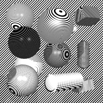
- Non-Photorealistic Rendering (NPR). For example you could implement Leister's Hatching method:
- Obtain inspiration for your own ideas here